Mobile
cabinet/trim shop construction
The three pictures below give you an idea of the head height and the skeleton and how it operates, though I rarely ran it up that high. Made the lumber racks too hard to reach and more area for the radiant heat to heat.

A full 8 foot.

Painting. Yuck! The hydraulic system will stop at any place and hold still while painting.

The welds were ground flat where the stainless sheet was to be screwed on.
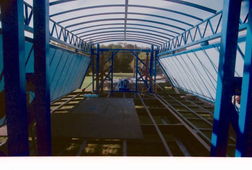
Each of the two extension wings to extend the roof and the floor moves independently. The height of the main structure also moves independent of the wings, and is raised by the large, red, vertical hydraulic cylinders at each end of the trailer. The large blue round pipes about 6 inches to the outside of the vertical hydraulic cylinders have another pipe inside of them which is what keeps the whole structure rigid when opened (they're the ones almost touching the roof). The home made trusses are welded to each end wall which is welded to the outer vertical blue pipes. The roof is Lexan for natural lighting during the day.

In above picture you can see that the floor is dropped down by the end hydraulic cylinders that are inside the trailer. The top structure is up a couple of feet. The horizontal bar in the foreground will be sitting on the trailer floor when the top is all the way down. You can just barely see (also in the foreground) the connection of the hydraulic cylinders that are outside the trailer, which operate the roof extensions.

Above is a shot of the outer cylinder partially opening the roof extension. Those wings are really heavy and are hung from four hinges I made from 3/8" thick wall seamless mechanical tubing. The hinge pins are 7/8th inch pipe. The cylinder is pushing on 2"x4" tube steel which is 2" wider than the roof. So it locks around the end wall when it is shut.
The reason for the huge hinges is that both the floor extensions and the roof extensions act as trusses when closed and on the road. So all the forces of the combined bumps and sways are transferred through the hinge pins to or from the frame and trusses.


There is only one valve that operates all 4 big cylinders that raise the whole thing up. The hydraulic oil comes out of the pump and goes through a "geared flow divider" that separates the oil into 4 "equal" parts by volume - not pressure. So if there is more weight on one cylinder , it will still go up as fast as all the other ones. If not done this way, and done by equal pressure instead of equal volume, then the cylinder with the lightest load would go up faster than all the others and cause the thing to rack and then self destruct, or get so stuck I could never get it back down.
The 4 things sitting almost on the tongue are adjustable pressure relief valves for each of those 4 big cylinders. The flow dividers have what is called "leakage" and the 4 "equal" parts are not exactly equal. So I stuck those in there so that I could even up all the 4 cylinders when I shut the trailer. They schreech like hell when they bypass oil back to the reservoir when I even up all the cylinders.
The gauge you see on the oil filter is a differential pressure gauge that tells me when the oil needs changing. (About 6 years ago now.) Am I an idiot or what?

The gauge facing to the front is a straight pressure gauge to give me the total system pressue reading. When I designed the hydraulic system (after I learned how hydraulics work), I realized that the starting point was electricity. I wanted a system that could operate on a 20 Amp 110/120 volt circuit so I could use a generator (or a kitchen house circuit) to open it if necessary. So 20 amps @ 110/120 was my starting point. The motor is only 2HP continuous duty cycle and draws just over 20 AMPs on 110. I have it wired 220 so it only draws half that per leg, but I can change it to 110 real quick in an emergency.
Then I just kept working up the line, juggling pump pressures against pump volume and computing different cylinder volumes till I got the max speed out of 20 amps. I bought a 2 stage pump, and it goes into low gear when it gets cold - but it still opens the trailer even when it's below zero out. Just takes twice as long.

You can imagine the weight that is on those 4 big cylinders.
Here's a picture of it taken from the middle towards the back door (the Mosler safe door) with the top structure closed all but a couple inches. You can see the green thickness plane's head sticking up. Note the 220 outlets on the left side about 14" up from the floor, one partially hidden behind the steel diagonal. They will be up at about 5' high when the roof is raised.The old shaper is next to it then a stand and the table saw in the foreground.
I gave that shaper away to a buddy of mine, and replaced it with a good Italian shaper. The Italians make shapers and power feeds second only to the Germans, and at a fraction the cost. Two halogen lights are on the end wall (two more on the other end) and what look like light fixtures on the sides are 4' long radiant heaters like sawyers use in all the little sawmills up here. They use one - I use six, having been born in Alabama and lived in the Everglades the first 13 years of my live. So I have 24 linear feet of heat in there.
I used to turn the heat on with the shop closed when it was real cold. One day I had to leave for some crisis or another and forgot about it. When I came back and opened up, a ring of toilet bowl wax with 3" screws in it was a puddle dripping all over everywhere.

This is looking to the front. I hadn't put in the lumber rack hanging from the ceiling when this pic was taken. My overhead air is not in either, that's compressed air - not air conditioning . That's a 100amp service entrance behind the jointer.

Here is looking from the jointer side with all the windows open. I have the rack in place now. The good lumber goes on top of the stainless round tubing. I didn't want the stock touching regular steel because I was afraid that nightime condensation would rust it and cause those black/purple stains on high tanin stock. Under it is 1x2 rectangular regular steel tubing that I stick clamps into and onto.

Here is looking a little toward the front. The chop saw pops out of the cantilevered stand when I run long stock through the shaper that has to go out the window.You can see the other window in line with the table saw. The long skinny window is for the jointer which has it's outfeed bed just peeking into the picture on the right. My entry ramp is coming up on the wing in the right of the picture.
That biscuit shaped thing right beneath the outfeed rollers is a hole in the floor. Under it is a piece of steel welded to the trailer frame like a keyhole. Four pieces of angle iron with an identical hole in each is welded to the base of each machine. Those two angle looking pieces of steel on the floor just beyond the shaper have heavy compression springs between washers and cross pins holding them in. I position the machines over the holes in the floor, shove those spring contraptions through the holes, turn them 90 degrees and they snap into a slot underneath the trailer. That way, I don't have to use a bunch of straps etc to get the show on the road.
That table saw is a Vega I bought back in '79. I don't think they make them any more. They were too expensive to make here compared to Deltas and Powermatics, and frankly not worth the extra money and weight. The roller stands are supported by the steel tubing that is in the racks on the saw. Those legs fit into larger steel tubing welded to the bottom of the saw. The rollers extend around the corner of the saw (or not, depending on what I'm doing), since each can be used separately.
Since they are perfectly aligned and registered off the saw itself, they never cause the stock to track wrong, like most roller stands.

Those colorful brackets above the jointer are really handy for when I'm joining stock. No moving around. The stock goes from the lower set to the upper set: and then from the upper set to the lower set till I'm done with that operation. The colorful cord plugged into the 4 way outlet up top towards the left feeds a 4 way outlet out at the end of the extension roof. That way the stuff I use on the cantilevered bench can be plugged in overhead - chop saw, router, etc. There are 4 four ways on each extension wing as well as four on the bottoms of each truss. So I have 64ea 110 outlets overhead. I don't like tripping on cords and have at least 4 outlets within reach without moving no matter where I am standing in the trailer. All my 220 outlets are on the end walls and move up to good height when the trailer is open.
The reason for all the color on those things is to remind me to remove them before closing up the shop. Crushing injuries to various components were a hazzard for the guys on my crew that used to shut down when I was off the job bidding another or something. What is at chest height when open is at floor height when closed. The closing force is about 50,000 lbs.

Dust sucker outside. Chop saw bed sticking out it's peep hole. Incidentally, the chop saw beds are white matt formica (good for sketching on) glued to Dow Blue and glued and screwed with stainless Eurohinge screws into a rabetted band of apitong that used to be my truck bed. 1/8th" plywood is on the bottom side attached the same way. They are super light, and do not deflect even with Tom ( who weighs about 240) sitting in the middle. The only entry door (when the trailer is closed) is the Mosler Safe door, seen above the drum sander, that I scrounged from the job where I built the trailer,and cut down with a torch to fit.

Drum sander - which I gave away last year. Ramp and door way.

On a job. Nice day. The only limit to stock length on any equipment or tool is external obstacles.

Give me a shout when you get a chance.